
LENSS: LOFAR Enhanced Network for Sharp Surveys
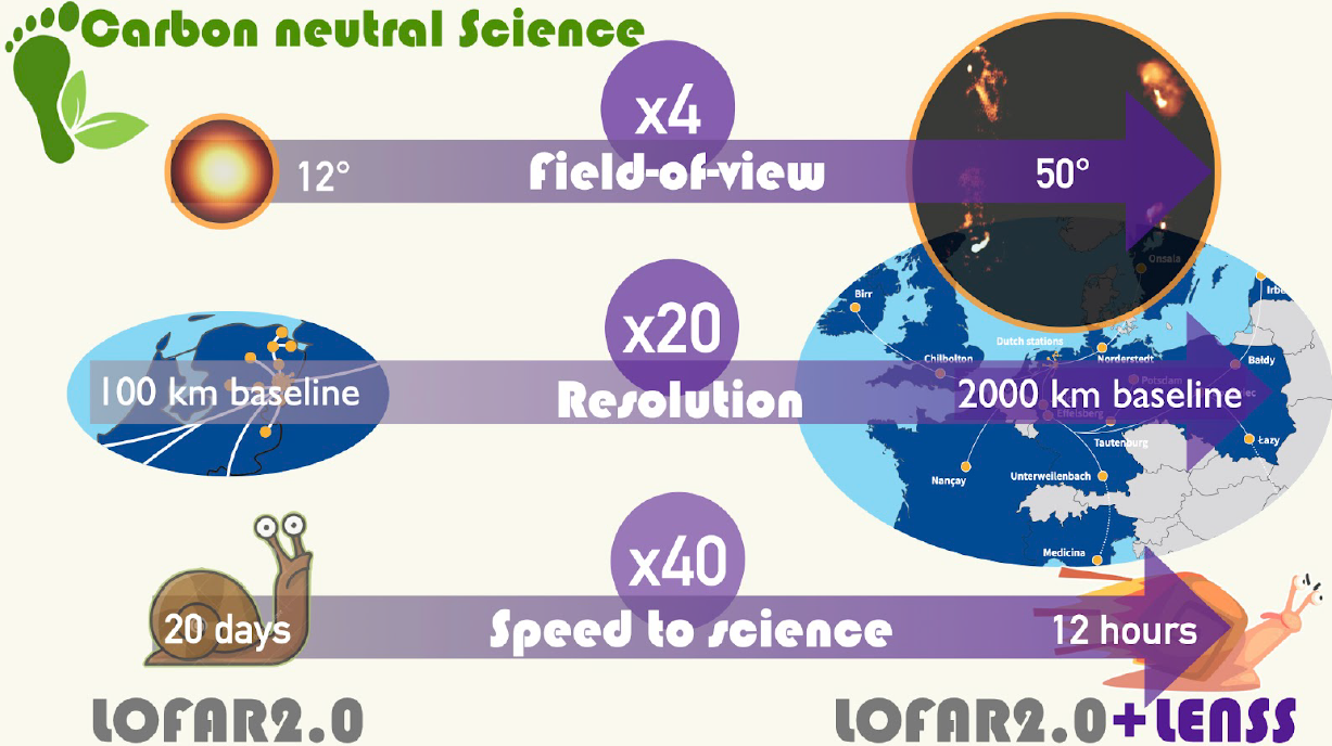
Very recently a Research Infrastructure (RI) proposal has been written for funding the next step of LOFAR and the SDC. LENSS proposes to quadruple the Field of View of LOFAR, while increasing the speed to science significantly. For LOFAR the station to central processing network bandwidth needs to be enlarged. But, more challenging is the processing of all that extra data. On top of that, we have set ourselves another challenge: to process the additional Field of View for the same energy cost. For that we aim in LOFAR to (1) optimize the correlator and beamformer for energy consumption and (2) streamline the pre-processing (flagging, A-team subtraction, averaging and compression). Also, the data quality control will be fully automated. The final goal is to stream the LOFAR data to SDC. SDC has its own challenges and needs acceleration to increase the speed to science. In particular, the long baselines are a challenge to process in a reasonable time for a reasonable cost.
The writing of the proposal was a joint effort of many people and now we keep our fingers crossed for the outcome.
Network Upgrade
Wilco Baan Hofman Julian Kootstra
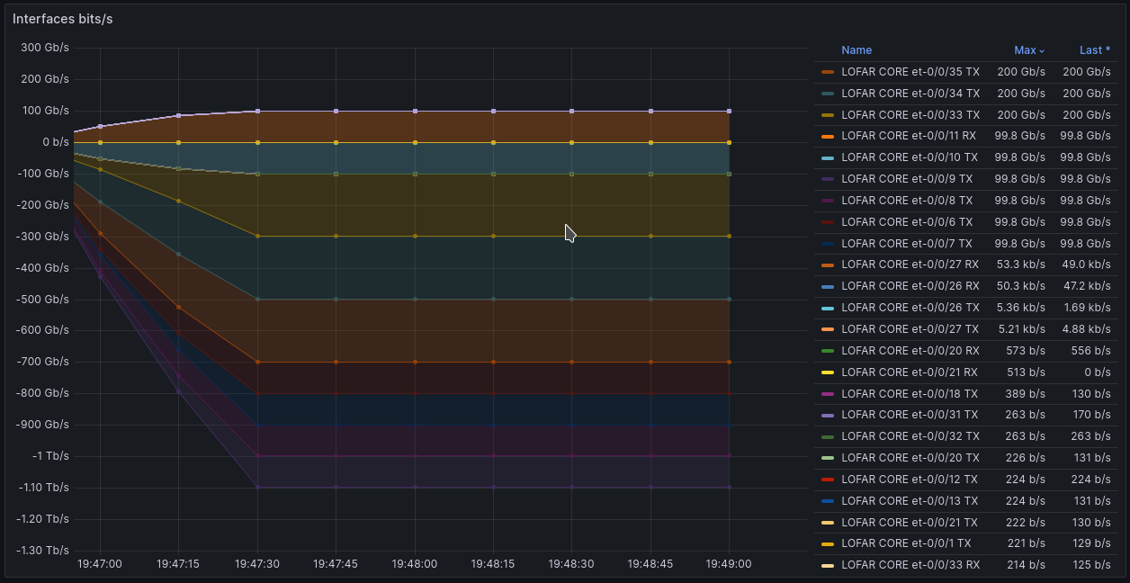
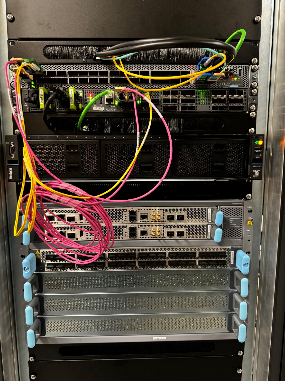
The LOFAR Network Team have been working tirelessly on getting up to 1.6Tbps of unique ingress multicast validated on the proposed new network core. The station switches have already been tested up to 200Gbps of egress traffic (required for future extensions) and work has begun on redesigning the LOFAR IP layer. Multicast is relevant for transposing the data before it reaches the GPUs, so that every GPU can work efficiently on the right antenna data, without having to communicate with other GPUs, it also enables other science cases to simultaneously work on the same antenna data. In the figure below a result is given for the multicast tests.
Finally work has begun on forming a workgroup with ASTRON and SURF to start upgrading data paths to remote and international stations and moving all of our connections through SURF to 400G service ports.
Adding self-calibration for LINC Target HBA
For interferometric imaging science, the LOFAR Initial Calibration pipeline (LINC) is one of the first pipelines that touch the data. It corrects for systematic effects and direction-independent ionospheric effects. The quality of the calibration solutions that are derived here sets the precedence for all further processing that uses them. In general, errors introduced here are hard or impossible to correct later on.
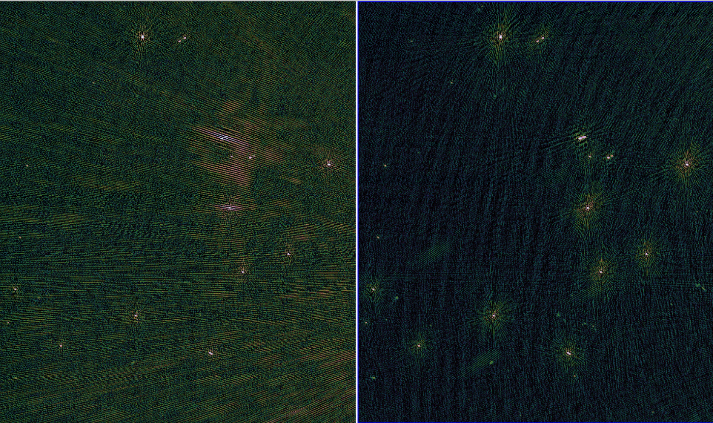
One of the main limitations is the use of only TGSS ADR1 as a calibration model. To address this, the option to perform direction-independent self-calibration has been added to the HBA Target pipeline. After starting from TGSS ADR1, this will make a 6” angular resolution image and then calibrate against this updated model. This yields a substantial improvement for complex fields with barely resolved bright sources or complex diffuse emission such as the galactic plane or similar.
The figure below shows a comparison between TGSS only (left) and self-calibration (right) on an arbitrary patch of sky near 3C 295 as part of a targeted observation of the latter.
DANTE
Carla Baldovin and DANTE team
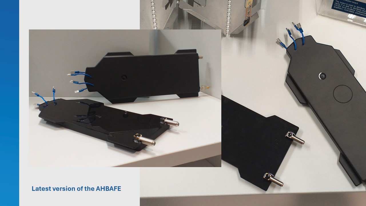
Over the past period, there has been considerable effort into finalizing the AHBAFE design. An issue with the performance of the AHBAFE was encountered at the end of 2023 (see previous newsletter). This led to a delay of ~5 months in the production of the next iteration of prototypes by an external manufacturer.
The design has matured using the LNA board prototype. Apart from validating the LNA circuitry the current measurement and EEPROM with NFC and ESD protection has been validated. All changes and optimizations are now incorporated in the final design. During the re-design work, we reduced the number of unique components to further reduce the board’s final cost.
The bill of materials (BOM) has been completed. The BOM is a comprehensive inventory of the raw materials, parts and components, and the quantities of each needed to produce the AHBAFE. The BOM needs to be carefully completed, since it will be used by the manufacturer in the production runs. This work is completed alongside the design and whenever components are changed or new ones are added, the changes need to be transferred to the BOM.
We did an accelerated lifetime test on the LOFAR HBAFE and the DANTE AHBAFE. During this test, the samples are subjected to humidity and temperature cycles including some freeze cycles. The tests run for ~1500 hours which is equivalent to ~7.5 years in real time. The LOFAR HBAFE is tested to confirm that the method chosen can reproduce the failures observed in the field.
The tests show that every geometry bridging the potting from the PCB to the outside environment is a potential risk for water entering the PCB. Due to a difference in thermal expansion between the potting material and the geometry that is interfacing with the outside environment, minuscule cracks occur, creating a path for the moist to enter the PCB. Although this test cannot give us a definitive answer regarding the lifetime of the AHBAFE, it does provide important information that can be used to improve the design.
During April, the team has done several reviews of the DANTE design: layout, schematics and potting design had each a dedicated review. A Detailed Design Review was also held, where the overall design and tests results were discussed. The results of the reviews provide further confidence in the next step: the manufacturing of 80 prototypes that will be later integrated into 5 tiles. The goal of this iteration is to test the manufacturability of the AHBAFE at large scales.
AIVV
Carla Baldovin and AIVV team
Preparations for the Production Test Stations (PTS) are in full swing. The production test stations (RS307 and CS002) will be soon upgraded to LOFAR2.0 hardware. The PTS stations will be the first ones to be fully upgraded to LOFAR2.0 hardware, and they represent the last opportunity to make small changes to the design. They will also be used to validate the verification and rollout procedures.
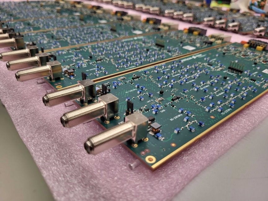
The team is currently working on the verification of the hardware. In Figure 1 the RCU boards and the test setup are shown. It is important to mention that the RCUs received were manufactured using the wrong material. If they are used in the upgrade, it is not possible to guarantee that they will perform according to the requirements. This risk is so high that it was decided to reject the boards. The manufacturer is now preparing a new batch of RCUs, we have now confirmation that the specified material is being used in their manufacturing. However, the RCU boards that were already delivered can be used to further verify the integration of the subrack.
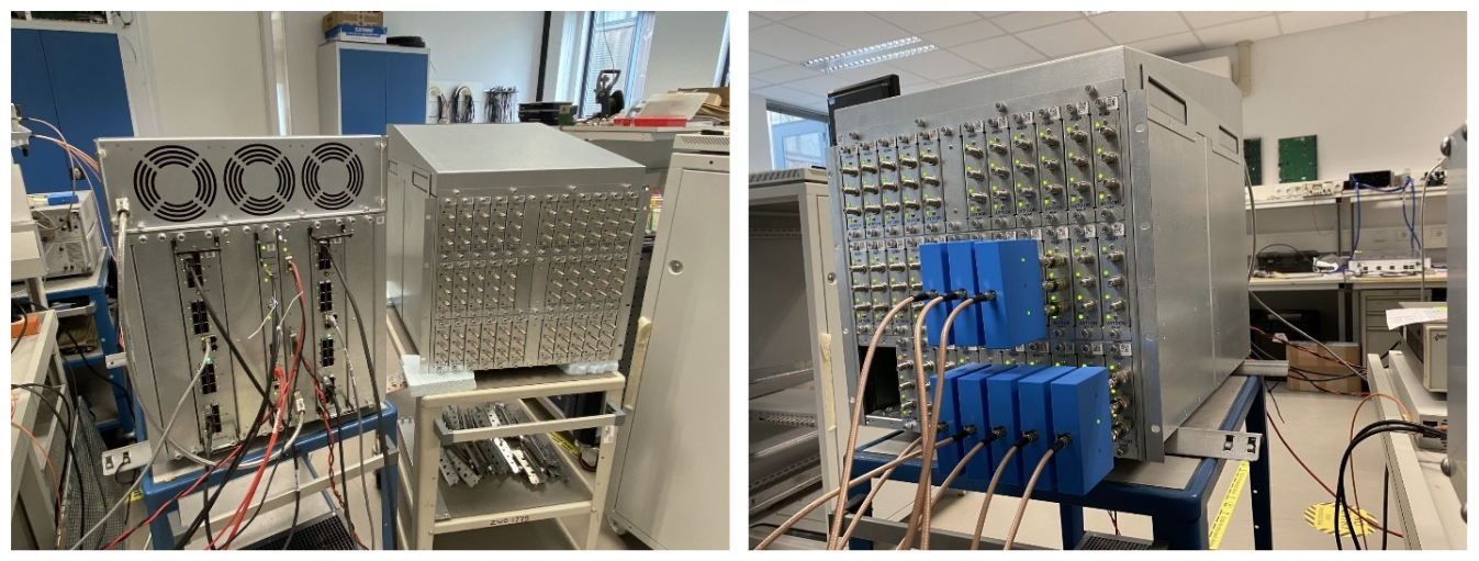
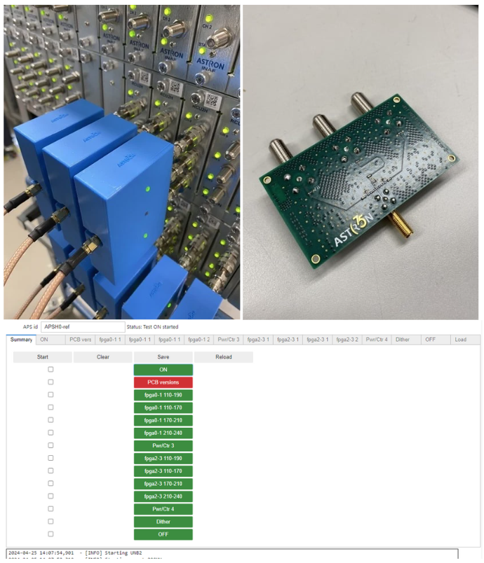
Figure 2 shows the setup used for the verification of the subrack, including a splitter used to apply equal test signal to an RCU. The GUI is displayed in the bottom panel.
In parallel to the verification of the hardware, the team is focusing in preparing the final details of the PTS upgrade: cabling, drawings, documentation, power supplies, maintenance, everything needs to be ready for the upgrade. The plan is to start preparing the stations in early May.
The first test station, L2TS, upgraded in 2023 is constantly being used by different teams:
- The science team is periodically taking observations to further understand the complexity of the new LOFAR2.0 system.
- Team Ruby continues developing the tools needed to successfully monitor and control the station, every week a new version of the software is rolled out.
- The hardware team keeps monitoring the behavior of the system and needs speed access to the station whenever is needed.
- The operations team needs to learn how the system works so they can be ready to successfully run operations when the upgrade is completed.
This requires coordination, collaboration and flexibility from all sides. To facilitate the interaction between the teams, the figure of the Telescope Operations Stakeholder is introduced. The Stakeholder makes sure L2TS runs as close as possible to a real operational environment, within the possibilities of the system at any given time. The Stakeholder signals issues to the right team and coordinates their resolution.
A set of procedures that the different teams follow when they need access to the station is also implemented. This includes informing the Stakeholder and requesting the Operators to make a reservation of the station using TMSS, which is the standard practice in LOFAR operations. In this way, we continuously improve the processes in preparation for the commissioning activities.

LOFAR Software Development
TMSS
Development for TMSS v1.1 is well on the way. Most changes are ‘under the hood’, as this version is mostly a Frontend-tooling update. We are updating many of the underlying packages to their latest version, and while we are doing that, we are removing a lot of duplicated-code parts. This has resulted in 1000-s of code lines being deleted already, so it is quite a formidable improvement from a maintenance point of views.
We also continued to adapt the QA (Quality Assurance) workflow to the needs of the Operators, who are now largely responsible for executing this workflow in the Cycle-20 projects.
Station Control Software
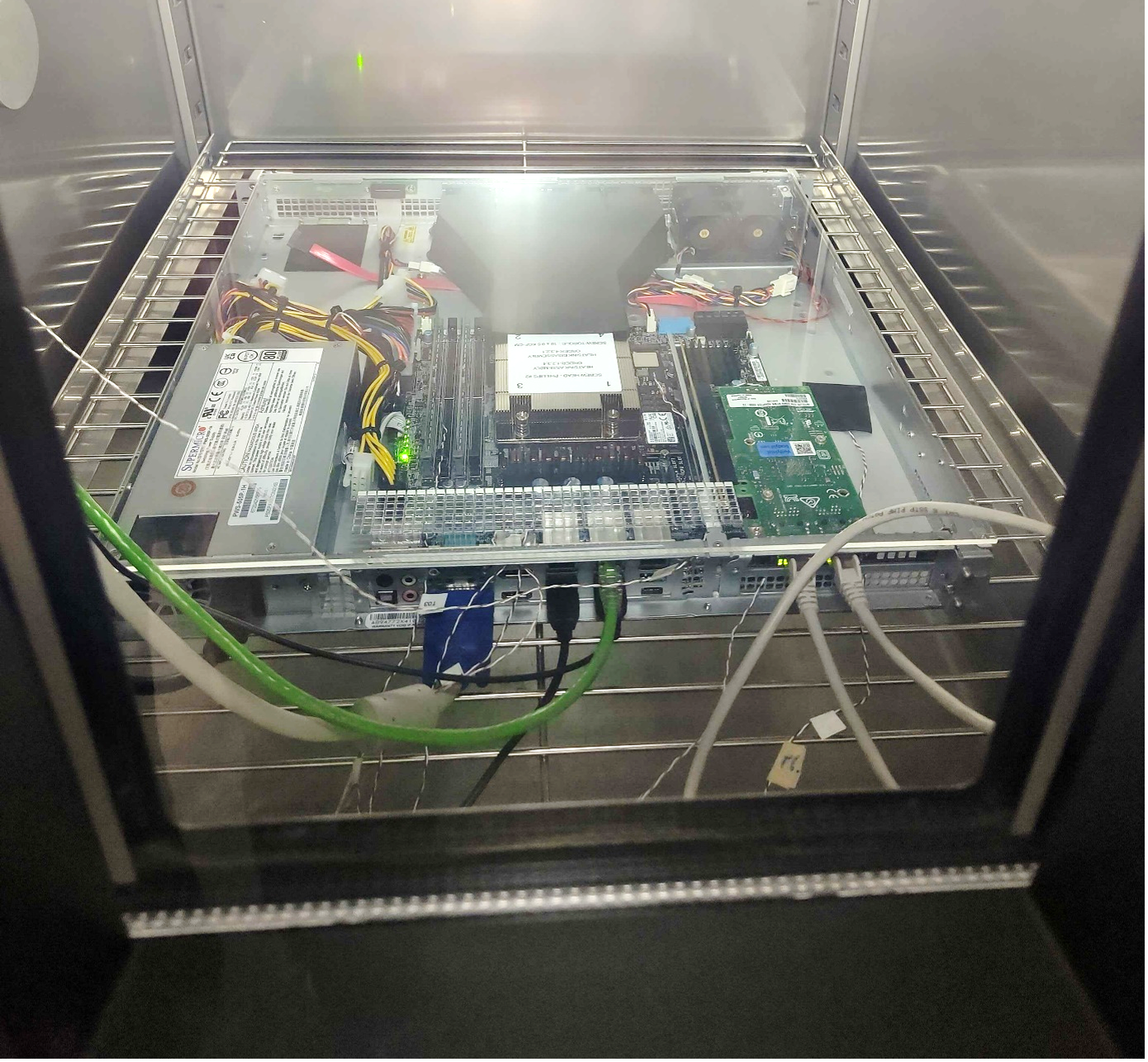
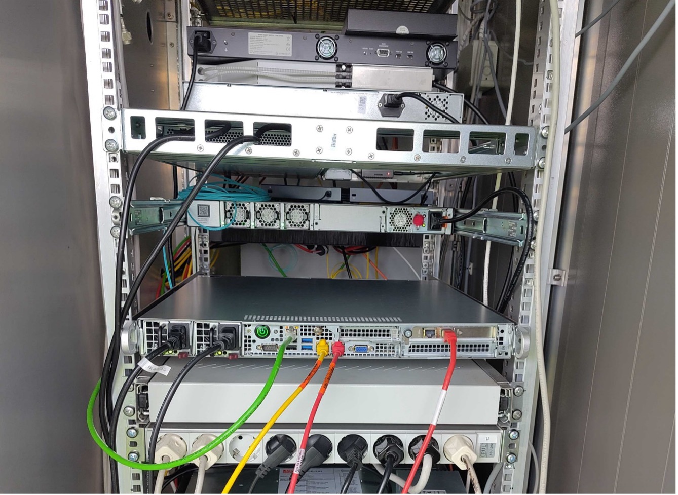
The selection of the LCU2 for the new stations is progressing. We did temperature resilience tests in the ASTRON climate box (see Figure) and are quite happy with the outcome. Another system has been placed in the cabinet of L2TS and is now running the monitor and control software for L2TS. We are in the process of testing alternative network cards; once we have done that, we will purchase a final test system with the configuration we prefer for the rollout and test that in one of the PTS stations.
Meanwhile we are supporting commissioning in L2TS and have setup a more robust and functional system. Much progress was made over the last weeks, though at the cost of spending quite some time on delivering this user support. The central services are now running on our new server. This will allow us to setup the two new PTS stations.
But as a result, we have not been able to deliver the central writing of station calibration files, yet, nor the antenna-delay calibration pipeline. In consultation with the commissioning team, the delivery of these capabilities has been postponed now. They have been integrated in the planning for the next Planning Increment, PI-3.
In PI-3, which runs from April 16th to July 9th, we focus mainly on PTS rollout, verification, and validation support, and in support for operations processes on these stations. Going from a single test station to three test stations will undoubtedly reveal unexpected issues. We are looking forward to identifying and solving these, as a first next step to a full LOFAR2.0 system.
CEP project
In the past months, the CEP project team has worked very hard on finalizing the decisions for the COBALT and CEP design. Several busy days have been dedicated to discussing the CEP storage solutions, CEP support for LOFAR2.0 commissioning, and most importantly, the performance of the COBALT software on the latest GPUs and optimizing the architecture. The latter is a challenging task in the very volatile and AI dominated GPU market.
We were excited to learn that the current COBALT software operates on all existing GPU platforms, though some platforms clearly perform better than others. Of course, we also would like to capitalize on the development of the TensorCore library, and therefore we performed an in-depth assessment of the risks associated with several implementation options for the new COBALT3. It was decided that a TensorCore correlator and beamformer kernel will provide the best balance of innovation, increased scientific exploitation and limited risks. A dedicated team within CEP project is responsible for the implementation of this component in the COBALT software.
Currently the focus of the team is on writing the tender for the CEP hardware, which we intend to publish before the summer. In addition, the network components for CEP have arrived at ASTRON earlier this year, and are undergoing acceptance testing. This includes the concentrator node switch and the core network switch.
SEE ALSO: